Category Archives: Dubious electronics

Disabling/enabling AES (power saving) programmatically on Victron inverters with Node-RED

Want to do this yourself? Grab everything you need from my Github!

Living off-grid means we have to be pretty careful with our electricity usage, especially in the winter when solar output can be a tenth of the summer highs. We don't have a huge number of mains appliances (fridge, laptops, coffee grinder, blender) and run as much as possible off 12 volts. Despite this, I honestly don't think we're missing out on anything! We use around 1kWh of electricity per day, just an eighth of the average UK household that Ofgem reckons uses 2900kWh each year.

One reason I chose to install Victron gear is that I am simply too lazy to turn an inverter on and off whenever I want to use mains power. Their inverters have a power-saving function they call AES (automatic economy switch), which keeps the inverter off and blips the power every second to see if a load is connected. If it detects a load, it switches on fully. This does restrict your choice of appliances to those without too many electronics, but for a fridge with an old-school bimetallic strip thermostat it works great.

The energy savings from using this "search mode" can be quite significant. My Multiplus 1600W inverter uses 10W when switched on with zero load, and 3W in power saving mode. Just considering the fridge, it tends to run in a 1-hour-off, 20-minutes-on cycle. So that's 18 fridge cycles per day, saving 7W * 18 hours = 126Wh compared to the inverter being left on 24 hours per day. That works out to an eighth of our average daily consumption saved. It's a much bigger deal in the winter, where the average day only gives us around 250Wh of solar power, so we're saving fully half of that!

The only downside is that picking the wattage thresholds to turn on fully can be quite finicky. These inverters don't have a current transformer on the AC output, so the power usage they report is just an estimate based on battery current and efficiency. Reactive vs resistive loads will also skew this figure. Choosing the threshold takes a bit of experimentation to pick the lowest wattage where the inverter will go into power saving with no load, but still switch on when something's plugged in. This seems to vary between inverters, but a good place to start is 25W and work upwards until it works well. Mine is just about right at 35W start and 67W stop (in reality this means a 10W load will keep the inverter on).

It's still not quite perfect, though. I noticed that newer USB-C laptop chargers will draw just a few watts to begin with, ramping up to full power after about 10 seconds. Since the "blips" in search mode only last for one AC cycle, they don't draw enough power to fully turn on the inverter before they reset. My lazy solution was to run the coffee grinder for a few seconds, but ideally I'd like to briefly disable AES, allowing the charger to ramp up before re-enabling it.

I've been playing with Node-RED a lot recently, so I figured I could find a programmatic solution. Problem is, there's a (sensible) divide in what Victron lets you access externally - you can change state but not settings, and AES is a setting so no dice. Luckily I came across this hacky workaround, which uses a digital input on the inverter to control the AES setting. The solution is described almost entirely there but took a lot of searching and keyword massaging to find, hence why I'm writing about it here!

Alright, enough backstory. This isn't a recipe website. tl;dr:

  • Add a relay to your GX device
  • Connect the relay to an input on the inverter
  • Add assistants to the inverter to use the input state to disable AES
  • Find some cute way to trigger the relay

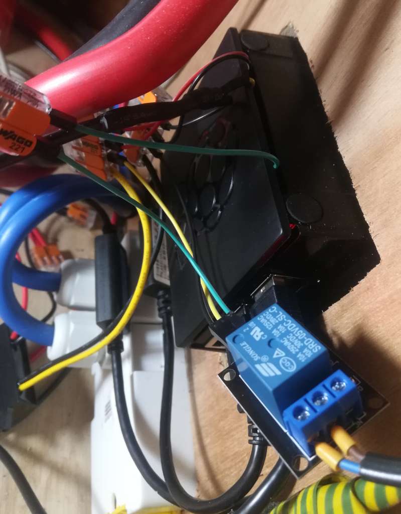
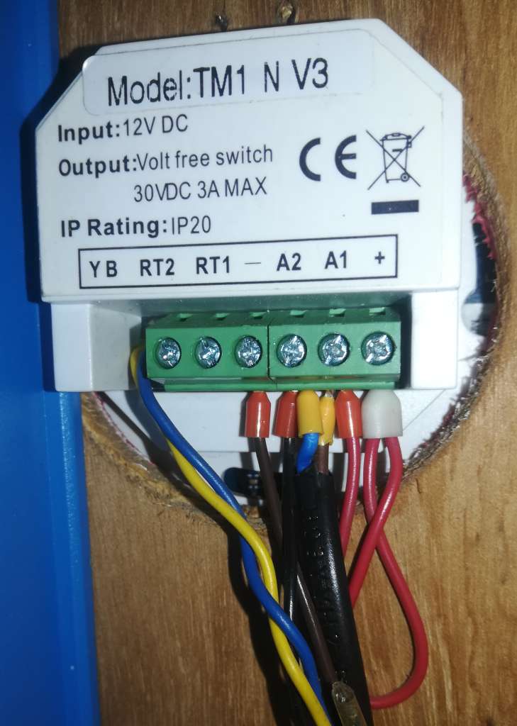
First things first is the relay. I run Victron's Venus OS on a Raspberry Pi, so an external relay module is needed (GX devices have one or more built in). By default the Pi build only comes with one relay output, assigned to GPIO21 (pin 40), and I was already using that for my heating. Easy solution: install Kevin Windrem's SetupHelper then RpiGpioSetup, adding 5 more relays (though only 4 total are accessible through Node-RED).

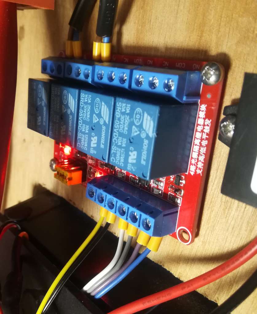
I then switched out my 1-relay module with a 4-relay one. For single relay modules, it seems like any old 5v relay module will do (they must be powered by 5v, but a 3.3v GPIO will trigger it). But when you go larger, you have to be careful - many of these seem to be active-low rather than active-high, and additionally require 5v to trigger them. Active-low doesn't work for Venus OS, as during the Pi's startup your relay will be turned on even if you invert its output later. So when you're looking for a relay module, avoid ones with a "JD-VCC" jumper (these require modification to work with 3.3v signals) and pick one with a set of configurable active-low/high jumpers (mine are labelled LOW-COM-HEIGHT, ha!).

Connect DC+ to the same 5v power supply as your Pi, DC- to ground, and IN1 to IN4 to the GPIO pins. If you're using the RpiGpioSetup package, these will be GPIO21, 17, 27 and 22 (header pins 40, 11, 13 and 15). The full list is here. Make sure the low/high jumpers are set to high.

Installing the 4-channel relay module

Next, set up the inverter. My Multiplus 1600 is a smaller model without digital inputs, but it does have an input for a battery temperature sensor which can be reconfigured. Since mine is connected to the Pi via a VE.Bus to USB cable, it uses data from the battery monitor for temperature-compensated charging, so this input is spare.

You can use Victron's VEConfigure software over USB, but if it's connected to the Pi it's much easier to configure remotely through the VRM. Go to Device list -> Remote VEConfigure and click Download to get the config file. Open VEConfigure, choose Port selection then Fake target from file and pick the downloaded file.

First, go to the Virtual switch tab and set Do not use VS (it's incompatible with assistants). Then, go to Assistants, add a General flag user and click Start assistant to configure it. Do the same again to add two Programmable relays. Configure them as follows:

General flag user:
- Use general flag to disable AES
Programmable relay:
- Use general flag
- Set relay on
- When temperature sense input is closed for 0 seconds
Programmable relay:
- Use general flag
- Set relay off
- When temperature sense input is open for 0 seconds

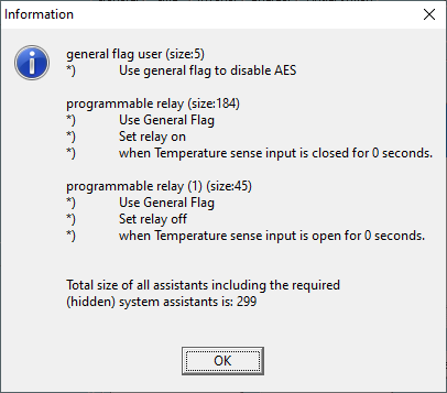
The "general flag" is a virtual switch that you can use to activate various features. Here, we use it to disable AES when it's "on". We then use a programmable relay to activate the flag when the temperature sense input is shorted, and another to deactivate it when it's open-circuit.

Close VEConfigure (don't use the save function in the menu), and save the file when prompted. Go back to the VRM, click Upload and choose the file. The inverter will reset a couple of times.

Now, connect the relay (COM and NO) to the temperature sense input. Either way round is fine. Use a small screwdriver to press in the orange tabs so you can insert the wires. I recommend ferrules if you want it to look neat!

Connecting the relay to the temperature sense input

The simplest solution would have been to connect a switch or button to the input to disable AES - flick the switch or hold the button for a few seconds until the load picks up. But since we're in it already, let's add a couple of buttons to our Node-RED dashboard.

Node-RED flow

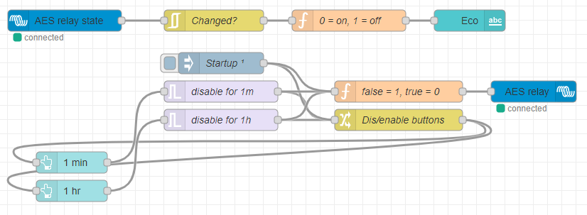
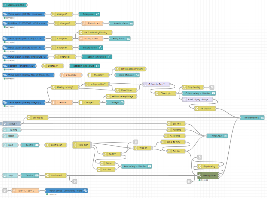
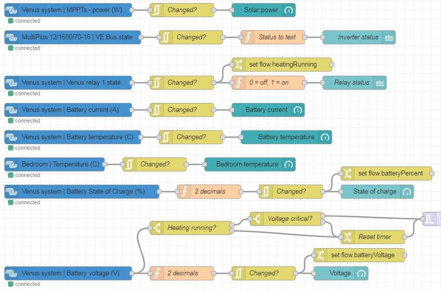
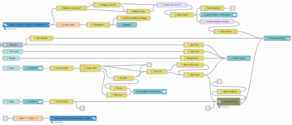
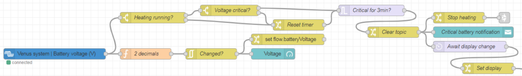
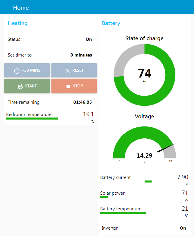
As usual, this is more complicated than it needs to be. You can grab the completed flow from my Github. I added two buttons, one for 1 minute and one for 1 hour. These activate trigger nodes, which send false immediately, then true after the specified time. false and true go to a change node, which sets msg.enabled from the payload and feeds this back to the buttons, disabling them until the timer runs out. They also go to a function node, which converts false to 1 and true to 0, activating the relay. I also added a relay state node which displays on the dashboard whether AES is on or off. Finally, I added a node which runs 0.1s after startup, turning off the relay and enabling the buttons in case the timer has been cancelled by a restart. Here's what it looks like in the dashboard:

Dashboard with AES on
Dashboard with AES off

And that's it! As always, drop a comment if you have any questions or made anything cool out of it 🙂

Run your Webasto from the internet with Victron’s Venus OS and Node-RED

Want to do this yourself? Grab everything you need from my Github!

If you live on a narrowboat, you'll definitely be used to being quite cold in the winter. There's not much worse than coming home late at night and knowing you're either going to have to spend an hour lighting the stove or go to bed wearing six layers!

Luckily, the previous owners of our boat were merciful and installed a Webasto diesel heater with radiators. We put a multi-fuel stove in anyway as a) it's very cosy and b) I don't trust it not to die in the middle of winter, but having the option of just clicking a button for heat saves a lot of admin. The only problem is, you need to be physically there to turn it on, which doesn't help you when you're on your way home and your house loses heat like a metal tube sitting in water. If you're in a house, you can of course just install a Nest or Hive or whatever. But everything is harder with 12 volts!

Last year I tore out the elderly electrics and batteries and installed the solar system of my dreams. Victron make a lot of fancy kit, but what I was most looking forward to was getting it all on the internet so I could stare at the battery voltage all day like the sad man I am. They make a range of GX devices to achieve this, but they go for hundreds. The good news is you can instead install their Venus OS on a Raspberry Pi, the bad news is the component shortage meant I had to wait an entire year to get hold of one.

Once I had everything hooked up, touchscreen and internet connection and all, the next step was to connect it to the heating. The most basic setup would be to use the built-in relay output and turn it on and off using the VRM control panel, but I wanted it a bit smarter so I didn't forget to turn it off (and ruin my batteries) or run it when the batteries are low (and ruin my batteries). Enter Node-RED, a simple but powerful way to virtually wire together devices and make lovely dashboards. It's included with the Venus OS large image and interacts with Victron kit out of the box so all I needed to do was put it together!

5V relay module
Installing the 5V relay module

Connecting to the heater was simple enough. I grabbed a cheap 5V relay module off eBay, and hooked it up to 5V power and GPIO21 (pin 40) on the Pi. The stock Webasto timer uses its own relay to connect the A1 and A2 pins together, supplying 12V to the black wire on the wiring loom which turns on the heater. I duplicated this, connecting the NO and COM pins on the relay module to A1 and A2 so I could still use the existing timer if needed.

Timer connections
Connecting to the stock timer (yellow-ferruled wires connect to NO and COM on the relay module)

I also installed a DS18B20 temperature sensor to keep an eye on the bedroom temperature. This integrates with the Pi and Victron's VRM using SetupHelper and VenusOS-TemperatureService: just connect it to 5V power (not forgetting to wire a 4.7K resistor between the + and signal pins) and GPIO 4 (pin 7) on the Pi.

Node-RED flows

Next up was the Node-RED flows. I overcomplicated this a bit for extra features and a nice dashboard, so I'll go through it bit by bit. If you want your own, you can grab the file and install instructions from my Github.

The built-in Victron nodes let you query and control all of your connected devices. I have a SmartShunt battery monitor and SmartSolar MPPT controller, both connected to the Pi by VE.direct to USB cables, and a Multiplus inverter, connected with a VE.bus to USB cable.

Victron nodes

The Victron nodes (blue) feed into dashboard nodes (teal). They push data every 5 seconds, or immediately on change, so first I filtered them to only update if they've changed. I also applied a couple of functions to convert numerical status to text, or reduce the number of decimal places. The relay status, state of charge and battery voltage nodes also set flow-context variables that are used elsewhere.

Heating control nodes

Next we have the heating controls. These are based around a timer node from node-red-contrib-stoptimer-varidelay. The +30 mins and Reset buttons edit a timer display, which is stored in another flow-context variable and pushed to the timer itself with the Start button. This also activates the heater relay. When the timer runs out, the relay is turned off again. The Stop button disables the heater relay and cancels the timer immediately. The Start and Stop buttons include a confirmation dialog to avoid inadvertently pressing them.

I also wanted to include some battery monitoring. The Webasto has its own low-voltage cutout, but this is set to something like 10.6V at which point your batteries are probably already wrecked. It's important to shut it down properly so it can clear the combustion chamber and cool down, so the safest way is to turn off the signal relay and let it finish up. When Start is pressed, I first check the battery voltage from the flow-context variable. If it's above 12.9V, the battery must be charging so we can skip the charge % check and start immediately. If it's between 12.1V and 12.9V, we move on to check the charge % (I like to check both as they get out of sync in winter when it's not fully charging every day). If it's over 55% (since you don't want to discharge lead-acid below 50%), we're okay to run. If the battery voltage is under 12.1V or charge % is under 55%, we pop up a notification and don't turn the heater on.

Battery checks while running

I also wanted to check the battery voltage while running: it's all well and good checking it at startup, but what if it gets dangerously low a few hours later? If the battery voltage drops below 11.85V while running and maintains that for 3 minutes, the heater will turn off.

I implemented this in the battery voltage flow. Each time the voltage updates, it will check if the heating is running. If so, it will check if the voltage has dropped under the critical level, and if so, will start a 3-minute timer. If the voltage rises again during this time, it will send a message to reset (i.e. cancel) the timer. This is important as the inverter or water pump starting up can cause the voltage to briefly drop under the critical level – but this doesn't mean the battery is empty!

I also included a connection from "Heating running? -> No" to the timer reset to avoid a race condition when the heating switches off. The "Heating running" switch checks the relay status, which doesn't update quite instantly when it changes. It was therefore possible that the 3-minute timer could start again, when the heater had already switched off but the relay status hadn't updated yet, thus sending another switch-off signal and notification 3 minutes later. The extra connection cancels the timer once the relay status has updated.

The final step was to put everything together into a nice dashboard. This uses the node-red-dashboard package, and node-red-contrib-ui-artless-gauge for some nice skinny gauges. I also added a tiny bit of CSS in a template node to make the confirmation dialogs look a bit nicer:

<style>
    .confirm-dialog .md-title {
        display: none;
    }
    .confirm-dialog .md-dialog-content-body {
        padding: 1em;
    }
</style>Code language: CSS (css)

And this is the final product!

Node-RED dashboard

The dashboard is accessible locally at https://venus.lan:1881/ui, or online via the Victron VRM (choose Venus OS Large from the left hand menu, then Node-RED Dashboard). So now all I need to do is flick the heating on an hour or so before I get home, and arrive to a toasty boat!

If you've done something similar, I'd love to see it! Drop a comment below 🙂

Cheap Chinese eBay antennas – a complete waste of money?

I live in a zoo. For the most part this is super cool, but it's in the middle of nowhere and the internet access leaves a bit to be desired. I started using a 3G dongle, but the signal is rubbish and it drops out whenever it rains.

3G signal

Zero bars, aww yeah

I started looking into ways to boost the signal, discovering that many mobile broadband users in rural Australia use Yagi antennas. These are highly directional and, if used correctly, can pick up signals from towers several kilometres away. I didn't have the tools available to DIY one, so turned to eBay for a sketchy Chinese alternative. What I got was this:

Continue reading