Want to do this yourself? Grab everything you need from my Github!
If you live on a narrowboat, you'll definitely be used to being quite cold in the winter. There's not much worse than coming home late at night and knowing you're either going to have to spend an hour lighting the stove or go to bed wearing six layers!
Luckily, the previous owners of our boat were merciful and installed a Webasto diesel heater with radiators. We put a multi-fuel stove in anyway as a) it's very cosy and b) I don't trust it not to die in the middle of winter, but having the option of just clicking a button for heat saves a lot of admin. The only problem is, you need to be physically there to turn it on, which doesn't help you when you're on your way home and your house loses heat like a metal tube sitting in water. If you're in a house, you can of course just install a Nest or Hive or whatever. But everything is harder with 12 volts!
Last year I tore out the elderly electrics and batteries and installed the solar system of my dreams. Victron make a lot of fancy kit, but what I was most looking forward to was getting it all on the internet so I could stare at the battery voltage all day like the sad man I am. They make a range of GX devices to achieve this, but they go for hundreds. The good news is you can instead install their Venus OS on a Raspberry Pi, the bad news is the component shortage meant I had to wait an entire year to get hold of one.
Once I had everything hooked up, touchscreen and internet connection and all, the next step was to connect it to the heating. The most basic setup would be to use the built-in relay output and turn it on and off using the VRM control panel, but I wanted it a bit smarter so I didn't forget to turn it off (and ruin my batteries) or run it when the batteries are low (and ruin my batteries). Enter Node-RED, a simple but powerful way to virtually wire together devices and make lovely dashboards. It's included with the Venus OS large image and interacts with Victron kit out of the box so all I needed to do was put it together!
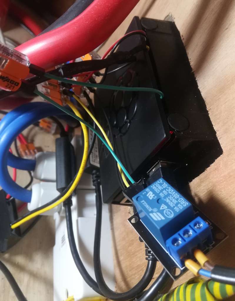
Connecting to the heater was simple enough. I grabbed a cheap 5V relay module off eBay, and hooked it up to 5V power and GPIO21 (pin 40) on the Pi. The stock Webasto timer uses its own relay to connect the A1 and A2 pins together, supplying 12V to the black wire on the wiring loom which turns on the heater. I duplicated this, connecting the NO and COM pins on the relay module to A1 and A2 so I could still use the existing timer if needed.
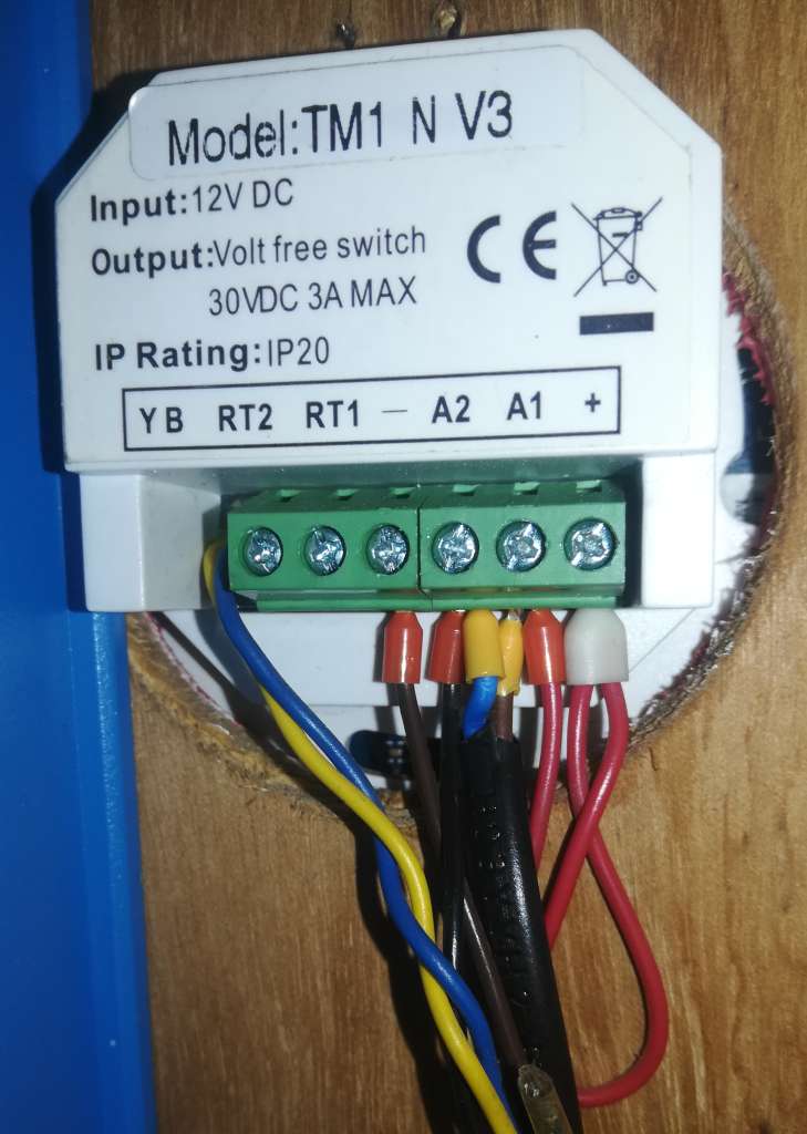
I also installed a DS18B20 temperature sensor to keep an eye on the bedroom temperature. This integrates with the Pi and Victron's VRM using SetupHelper and VenusOS-TemperatureService: just connect it to 5V power (not forgetting to wire a 4.7K resistor between the + and signal pins) and GPIO 4 (pin 7) on the Pi.
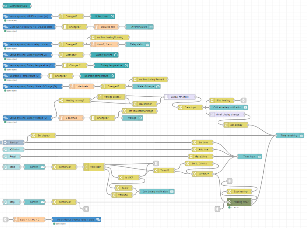
Next up was the Node-RED flows. I overcomplicated this a bit for extra features and a nice dashboard, so I'll go through it bit by bit. If you want your own, you can grab the file and install instructions from my Github.
The built-in Victron nodes let you query and control all of your connected devices. I have a SmartShunt battery monitor and SmartSolar MPPT controller, both connected to the Pi by VE.direct to USB cables, and a Multiplus inverter, connected with a VE.bus to USB cable.
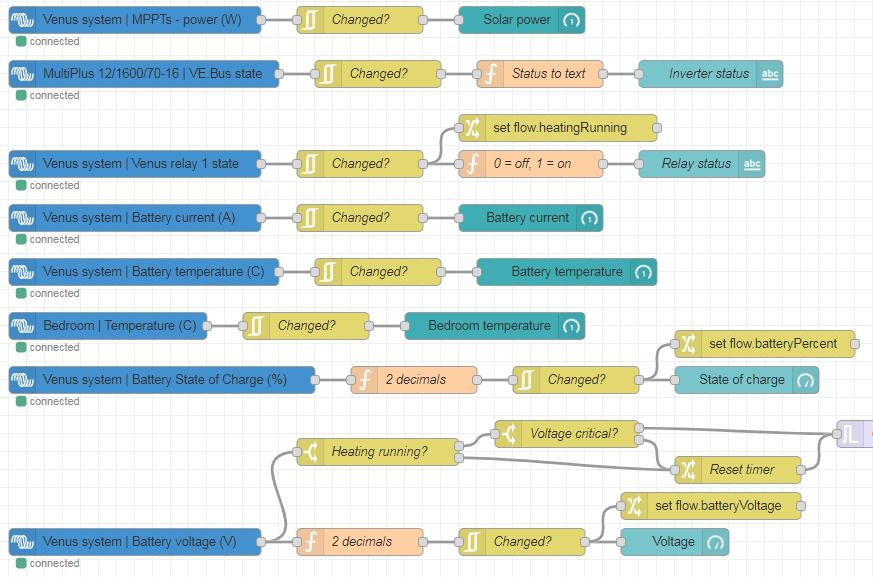
The Victron nodes (blue) feed into dashboard nodes (teal). They push data every 5 seconds, or immediately on change, so first I filtered them to only update if they've changed. I also applied a couple of functions to convert numerical status to text, or reduce the number of decimal places. The relay status, state of charge and battery voltage nodes also set flow-context variables that are used elsewhere.
Next we have the heating controls. These are based around a timer node from node-red-contrib-stoptimer-varidelay. The +30 mins and Reset buttons edit a timer display, which is stored in another flow-context variable and pushed to the timer itself with the Start button. This also activates the heater relay. When the timer runs out, the relay is turned off again. The Stop button disables the heater relay and cancels the timer immediately. The Start and Stop buttons include a confirmation dialog to avoid inadvertently pressing them.
I also wanted to include some battery monitoring. The Webasto has its own low-voltage cutout, but this is set to something like 10.6V at which point your batteries are probably already wrecked. It's important to shut it down properly so it can clear the combustion chamber and cool down, so the safest way is to turn off the signal relay and let it finish up. When Start is pressed, I first check the battery voltage from the flow-context variable. If it's above 12.9V, the battery must be charging so we can skip the charge % check and start immediately. If it's between 12.1V and 12.9V, we move on to check the charge % (I like to check both as they get out of sync in winter when it's not fully charging every day). If it's over 55% (since you don't want to discharge lead-acid below 50%), we're okay to run. If the battery voltage is under 12.1V or charge % is under 55%, we pop up a notification and don't turn the heater on.
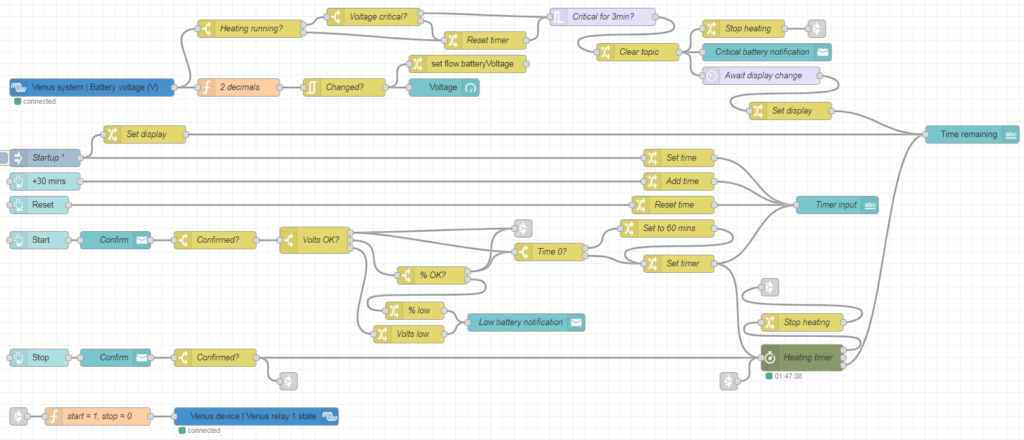
I also wanted to check the battery voltage while running: it's all well and good checking it at startup, but what if it gets dangerously low a few hours later? If the battery voltage drops below 11.85V while running and maintains that for 3 minutes, the heater will turn off.
I implemented this in the battery voltage flow. Each time the voltage updates, it will check if the heating is running. If so, it will check if the voltage has dropped under the critical level, and if so, will start a 3-minute timer. If the voltage rises again during this time, it will send a message to reset (i.e. cancel) the timer. This is important as the inverter or water pump starting up can cause the voltage to briefly drop under the critical level – but this doesn't mean the battery is empty!
I also included a connection from "Heating running? -> No" to the timer reset to avoid a race condition when the heating switches off. The "Heating running" switch checks the relay status, which doesn't update quite instantly when it changes. It was therefore possible that the 3-minute timer could start again, when the heater had already switched off but the relay status hadn't updated yet, thus sending another switch-off signal and notification 3 minutes later. The extra connection cancels the timer once the relay status has updated.
The final step was to put everything together into a nice dashboard. This uses the node-red-dashboard package, and node-red-contrib-ui-artless-gauge for some nice skinny gauges. I also added a tiny bit of CSS in a template node to make the confirmation dialogs look a bit nicer:
<style>
.confirm-dialog .md-title {
display: none;
}
.confirm-dialog .md-dialog-content-body {
padding: 1em;
}
</style>Code language: CSS (css)And this is the final product!
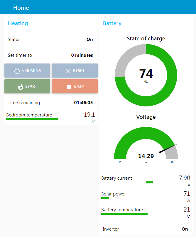
The dashboard is accessible locally at https://venus.lan:1881/ui, or online via the Victron VRM (choose Venus OS Large from the left hand menu, then Node-RED Dashboard). So now all I need to do is flick the heating on an hour or so before I get home, and arrive to a toasty boat!
If you've done something similar, I'd love to see it! Drop a comment below 🙂
Pingback: Disabling/enabling AES (power saving) programmatically on Victron inverters with Node-RED | asdfghjkl;'#